
Component derating is not optional — capacitors, MOSFETs, opto-couplers should be specified with margin against the worst-case temperature and voltage.
Automotive PCBA and harnesses for under-hood and cabin systems.
ECU, ADAS, BMS, and EV charging assemblies with traceable lots and sealed harness builds. We manufacture the electronics in the vehicle architecture, not the finished vehicle.
- IATF
- process logic
- AEC-Q
- component handling
- 100%
- harness continuity
- 10+ y
- BOM lifecycle planning
What we manufacture in this vertical
ECU PCBA for engine, transmission and body control units.
ADAS sensor and processing PCBA (radar carrier boards, LiDAR carrier boards, camera carrier boards).
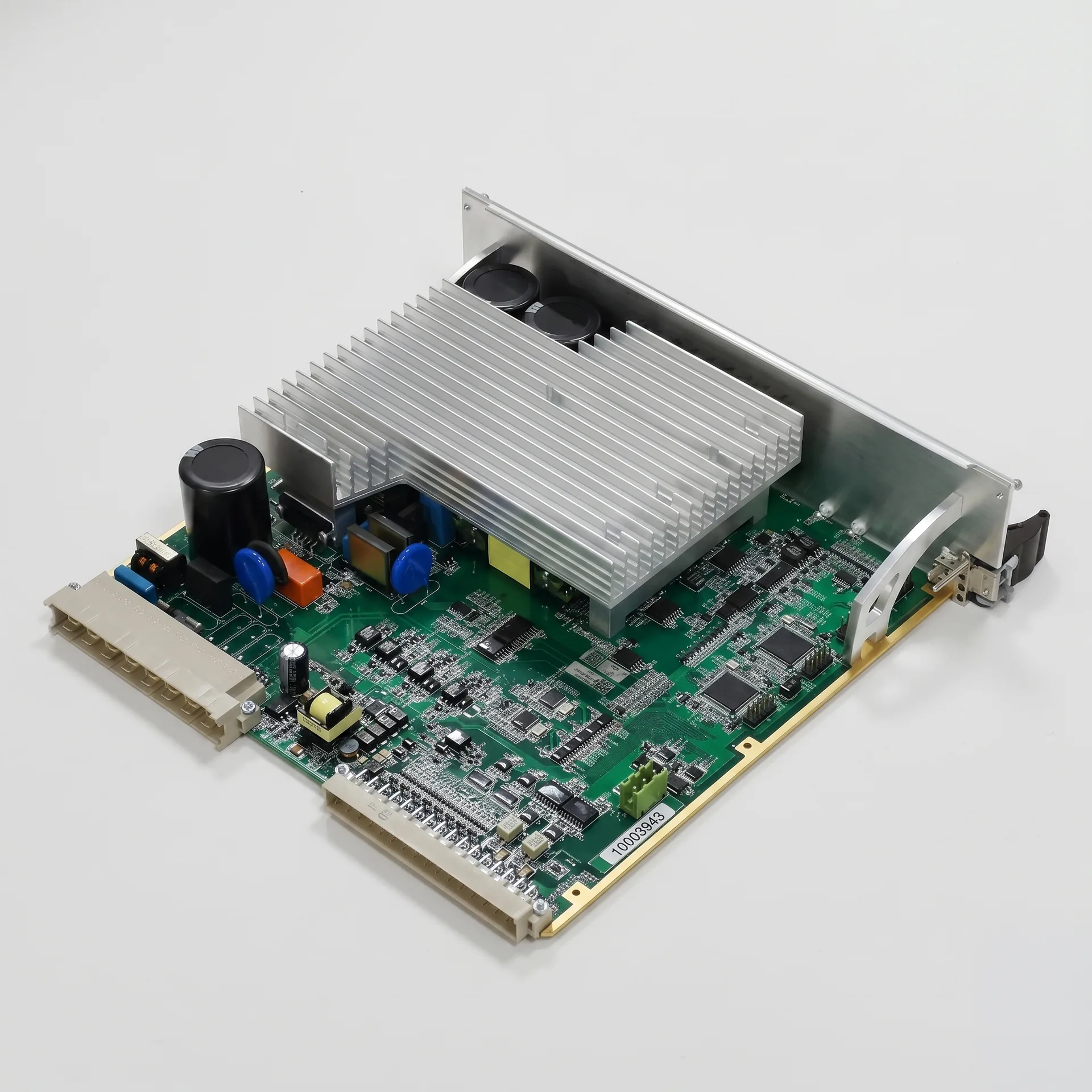
EV charging station power and control PCBA, including DC fast-charging.
Battery management system (BMS) PCBA.
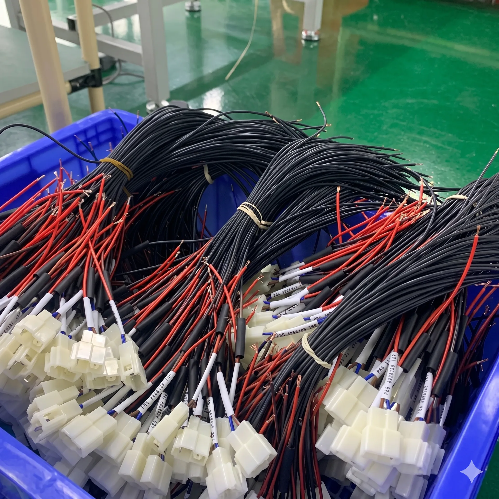
Sealed cable harnesses for trucks, buses and off-highway equipment.
Standards and compliance landscape
We do not certify products. We run the manufacturing line so that a customer's certification track is not blocked by manufacturing data, traceability or component sourcing.
Process discipline aligned with IATF 16949 logic across the line.
AEC-Q-grade component handling, ESD-controlled storage and dry-cabinet management.
Production records compatible with PPAP-style sample lots when requested.


Environmental envelope we build to
| Operating temperature (typical) | −40 °C to +125 °C |
|---|---|
| Vibration profile | ISO 16750-3 / customer-specific |
| Humidity | 85% RH at +85 °C, biased |
| Sealing | IPx7 / IPx9K achievable with potting and overmolding |
| EMC | Manufacturing-side controls (shielding, harness routing) per drawing |
Material and process choices common in automotive
- Aluminum-base PCB for power stages (LED drivers, BMS, motor inverters).
- Heavy-copper inner / outer layers (up to 6 oz) for high-current paths.
- High-Tg FR4 (Tg ≥ 170 °C) for under-hood thermal exposure.
- Conformal coating (acrylic, urethane, silicone) and selective potting for moisture and vibration.
- Selective soldering for mixed SMT/THT assemblies with sensitive connectors.
- Sealed connectors (Deutsch, TE Superseal, Molex MX150 family) overmolded in-house.
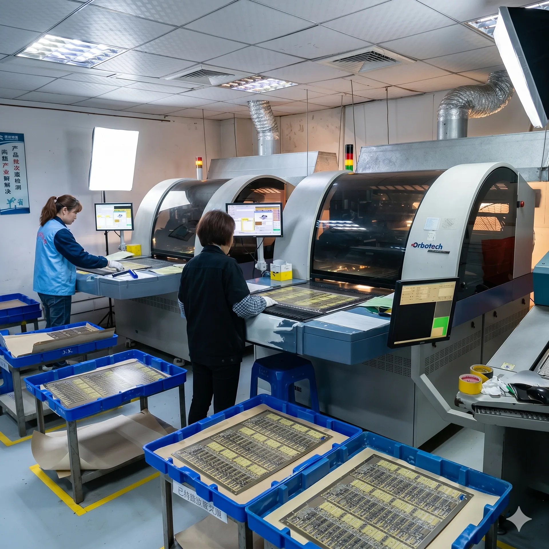
Built in our own factories
SMT lines, ovens and test stations are audited and MES-traced under one operation.
What changes versus a consumer-grade build
Single-source active parts are a real program risk in automotive lifecycles; alternates need to be qualified at design time, not at the first shortage.
Harness assemblies must be specified with sealing class and pull-force targets per crimp; informal drawings cause field failures.
Production sample lots may need to be retained for the program lifetime; this affects packaging and warehousing, not just the line.
What to think about before sending us files
- BOM annotated with manufacturer part number, alternates and AEC-Q grade where applicable.
- Conformal coating mask defined explicitly — connectors, switches, optical parts, programming pads.
- Test points exposed for ICT or FCT, on a single side where possible.
- Harness drawings with wire gauges, conductor counts, connector pinouts and a label sheet.
- Sealing requirements stated as IP class and the operating environment, not as free text.
- Serial-number scheme defined upfront (laser mark vs label, datamatrix vs QR vs barcode).
Documentation we expect in the manufacturing package
Gerber RS-274X or IPC-2581 / ODB++; drill files with units stated.
BOM in CSV or XLSX with reference designators and qualified alternates.
Assembly drawing with top/bottom views, polarity marks, fiducials, mechanical hold-down points.
Pick-and-place file with rotation convention and origin clearly noted.
Harness drawing with formboard scale and connector orientation.
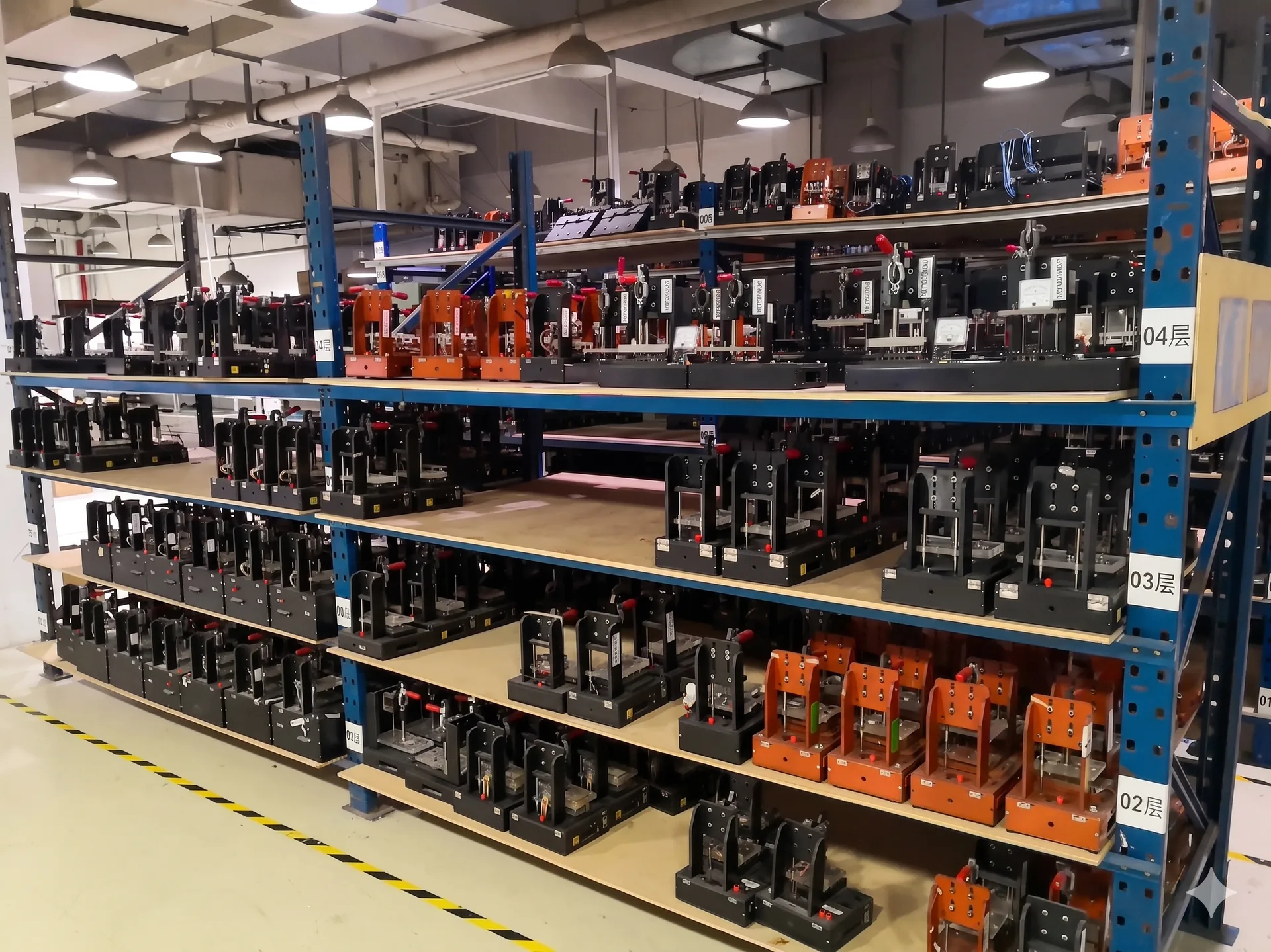
Test plan or FCT script outline (we can co-design fixtures from this).
Documentation we produce per program
First-Article Inspection (FAI) report.
AOI / X-Ray sample reports per lot.
ICT / FCT pass-fail logs per serial number.
Conformal coating coverage photos for the first article.
Harness continuity test reports per shipment.
8D reports for any closed defect during the program.
Common pitfalls we see in automotive handoffs
- 1. BOM lists a single distributor part with no alternates — the program runs out of capacity at the first allocation event.
- 2. Coating mask defined in a comment instead of a layer — operators interpret it differently across shifts.
- 3. Harness drawings without pull-force targets — first batch fails IPC/WHMA-A-620 sample test.
- 4. No defined serialization — late-stage retrofit is expensive and breaks traceability for early units.
- 5. ESD-sensitive parts not flagged in the BOM — handling line has to slow down to verify.
Representative cases
- Commercial-vehicle control module PCBA — aluminum-core board, paired sealed harness, IP-rated potting.
- EV fast-charger power PCBA — heavy-copper board with IGBT/SiC packages and matching high-current cable harnesses.
- ADAS radar carrier board — controlled-impedance stackup, BGA assembly, X-Ray on every lot.

Lead time and capacity notes
| Prototype PCBA (5–50 units) | from 10 working days |
|---|---|
| Pilot batch (100–1,000 units) | 3 to 5 weeks |
| Series PCBA (1 k–10 k / month) | 4 to 8 weeks lead, then steady cadence |
| Sealed harness pilot | from 2 weeks after formboard sign-off |
| AEC-Q parts on allocation | Risk surfaced during BOM review, not after PO |
Next step
Send your manufacturing package to start scope review.