Heatsink retention assembly with calibrated torque drivers.
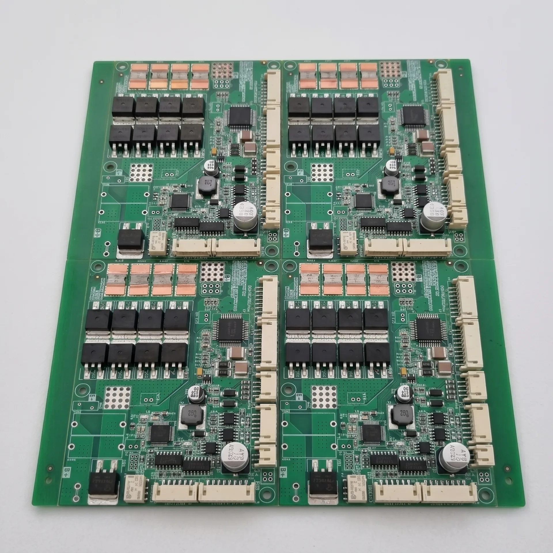
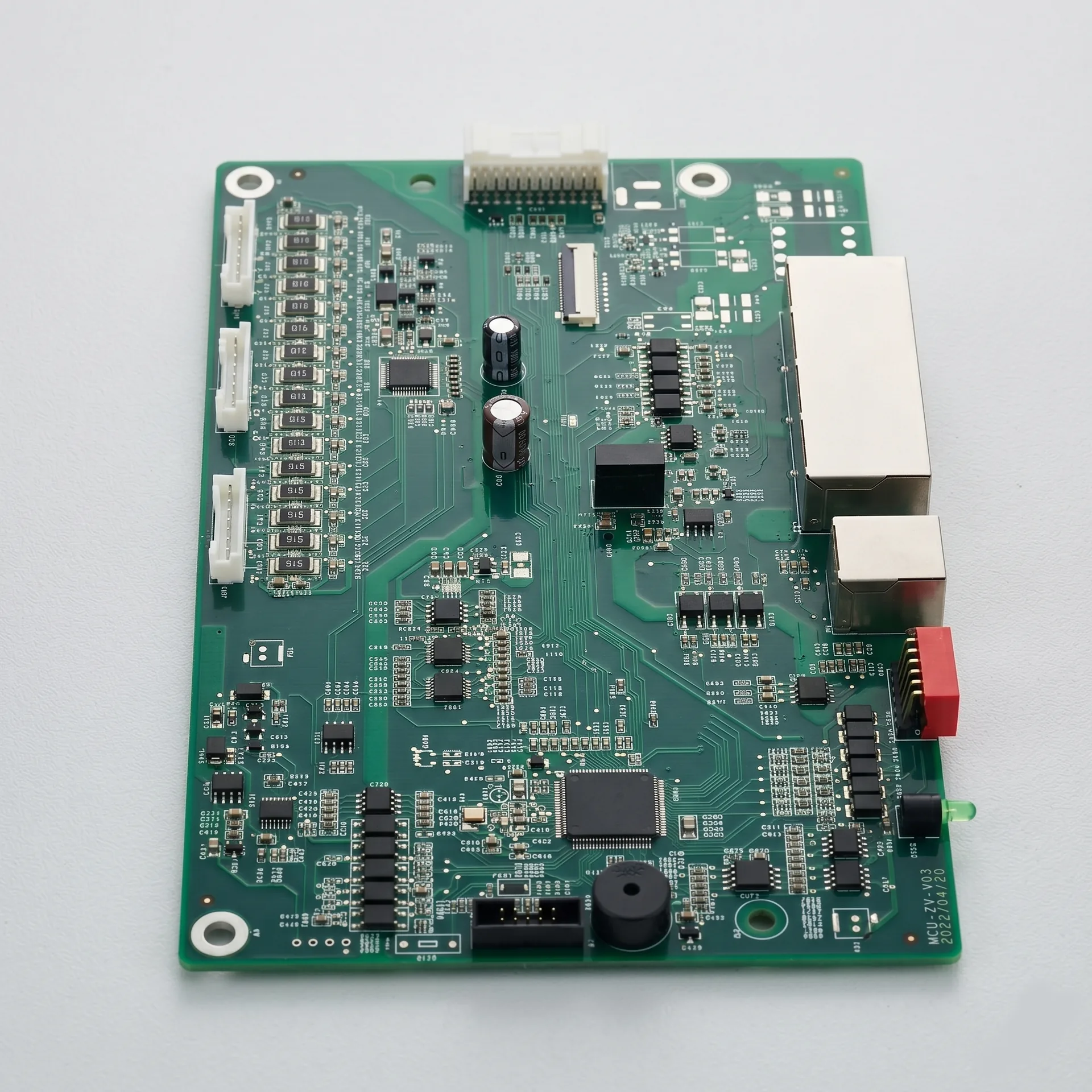
Computing PCBA for server boards, accelerators, and PCIe platforms.
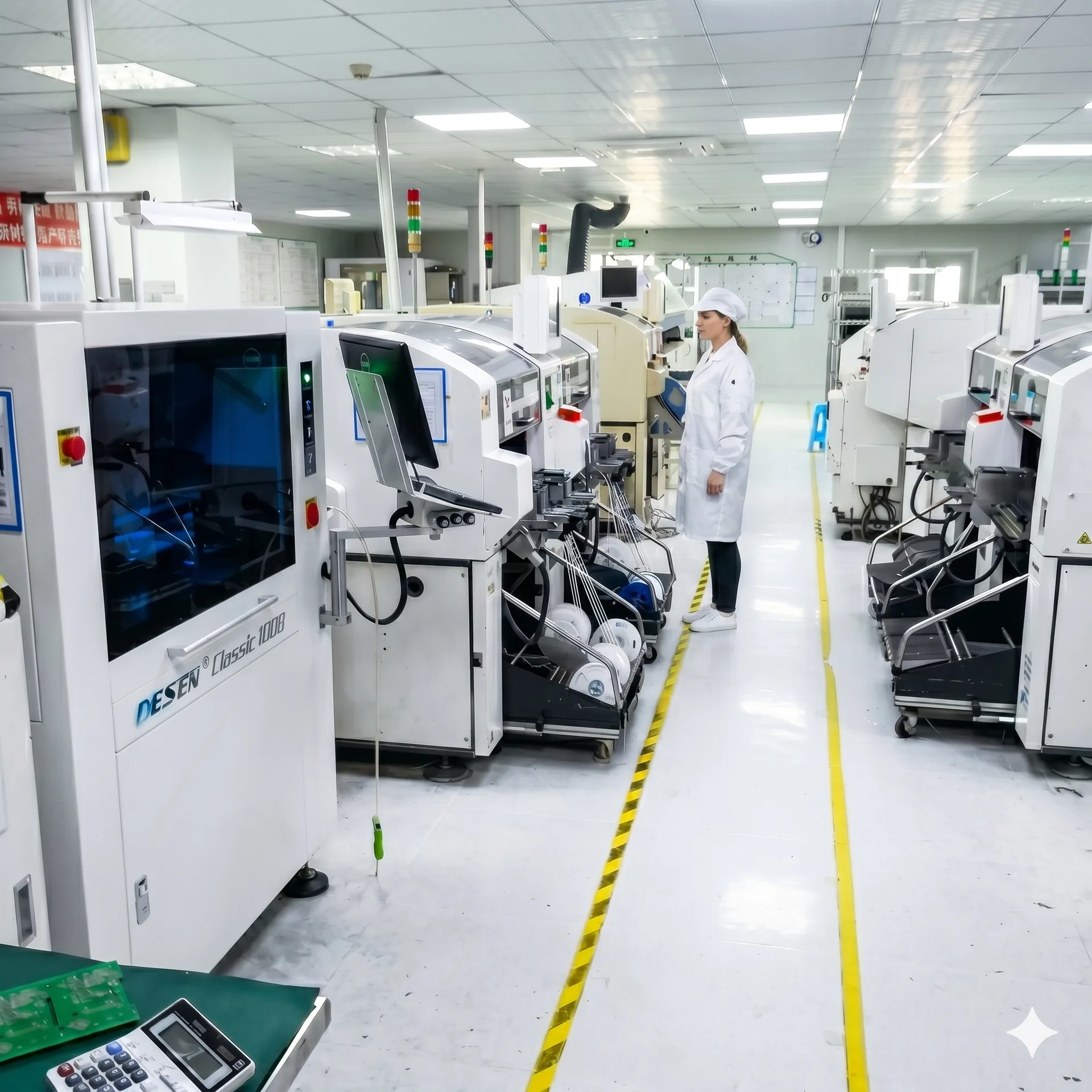
High-pin-count BGA assembly, signal-integrity-aware stackups, and serial-level test evidence for server and accelerator production.
- 16+
- layers, high-TG
- 2,000+
- BGA pins per package
- 100%
- X-Ray on critical lots
- Per serial
- FCT data retention
What we manufacture in this vertical
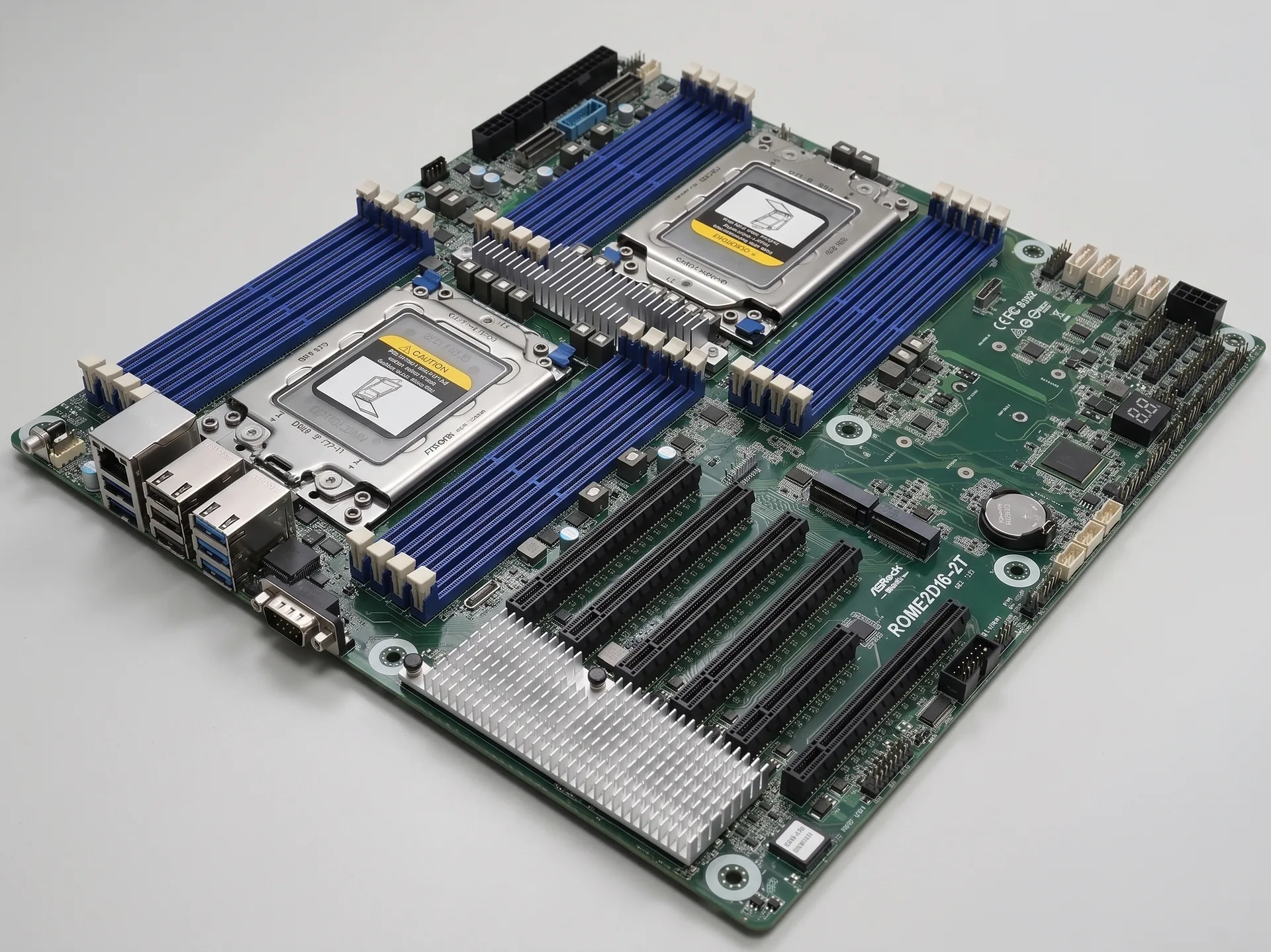
Server motherboard and dual-socket platform PCBA.
PCIe Gen4 / Gen5 expansion card PCBA.
Edge AI compute module PCBA (with GPU / NPU placement).
Back-plane and storage carrier board PCBA.
OCP-style mezzanine and accelerator carrier PCBA.
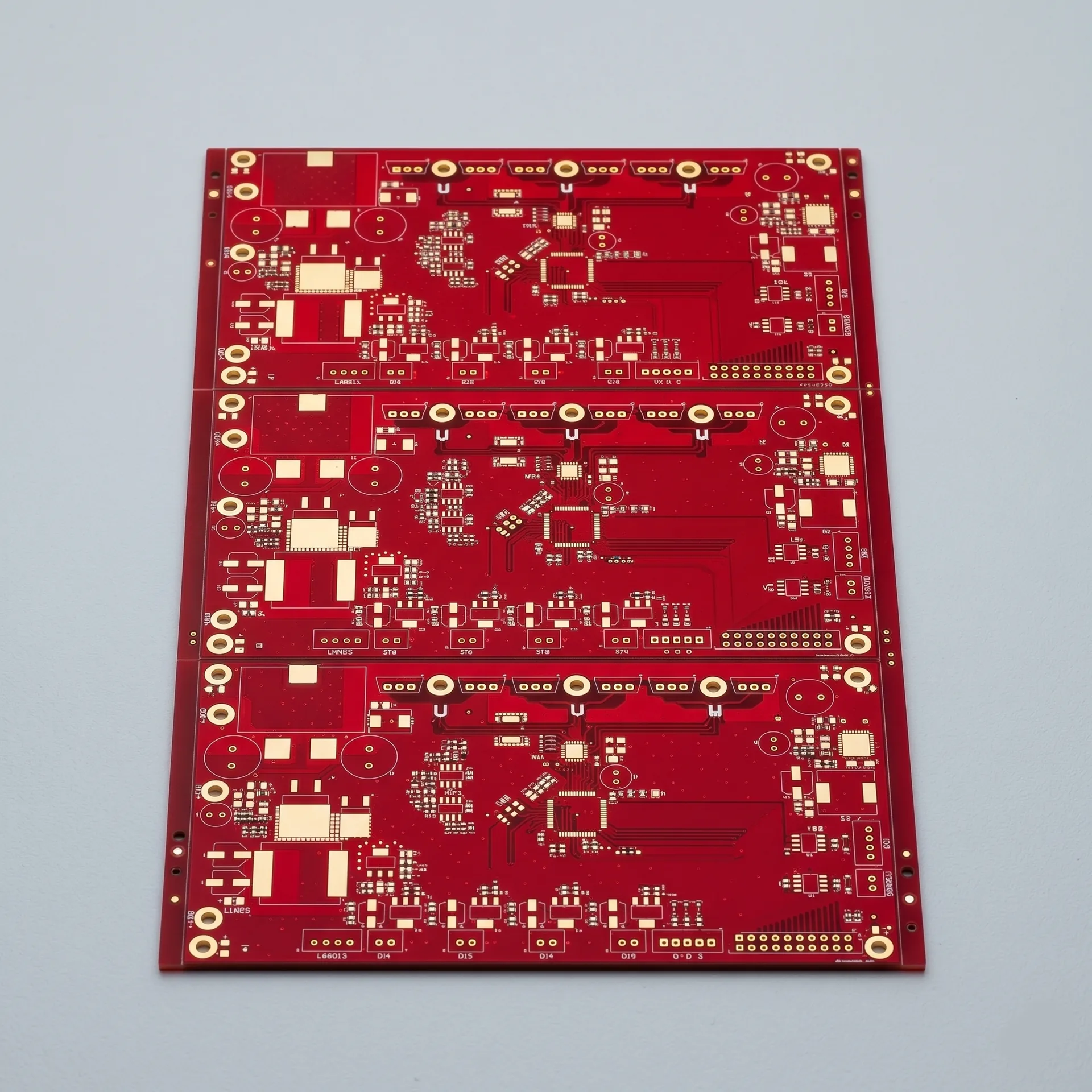
Stackup and material context
PCIe Gen5 (32 GT/s) and DDR5 push insertion-loss budgets into the territory where standard FR4 is no longer sufficient. The right material choice is a manufacturing concern as much as a design one.
16+ layer high-TG stackups standard; 20–24 layers common for dual-socket platforms.
Mid-loss FR4 for Gen3 / Gen4 short channels; low-loss for Gen5 and long-channel routes.
Hybrid stackups supported when only a portion of the board is high-speed.
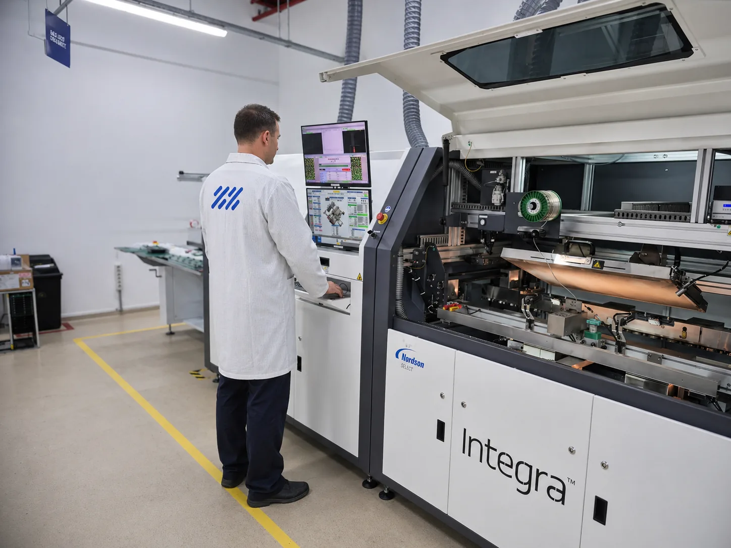
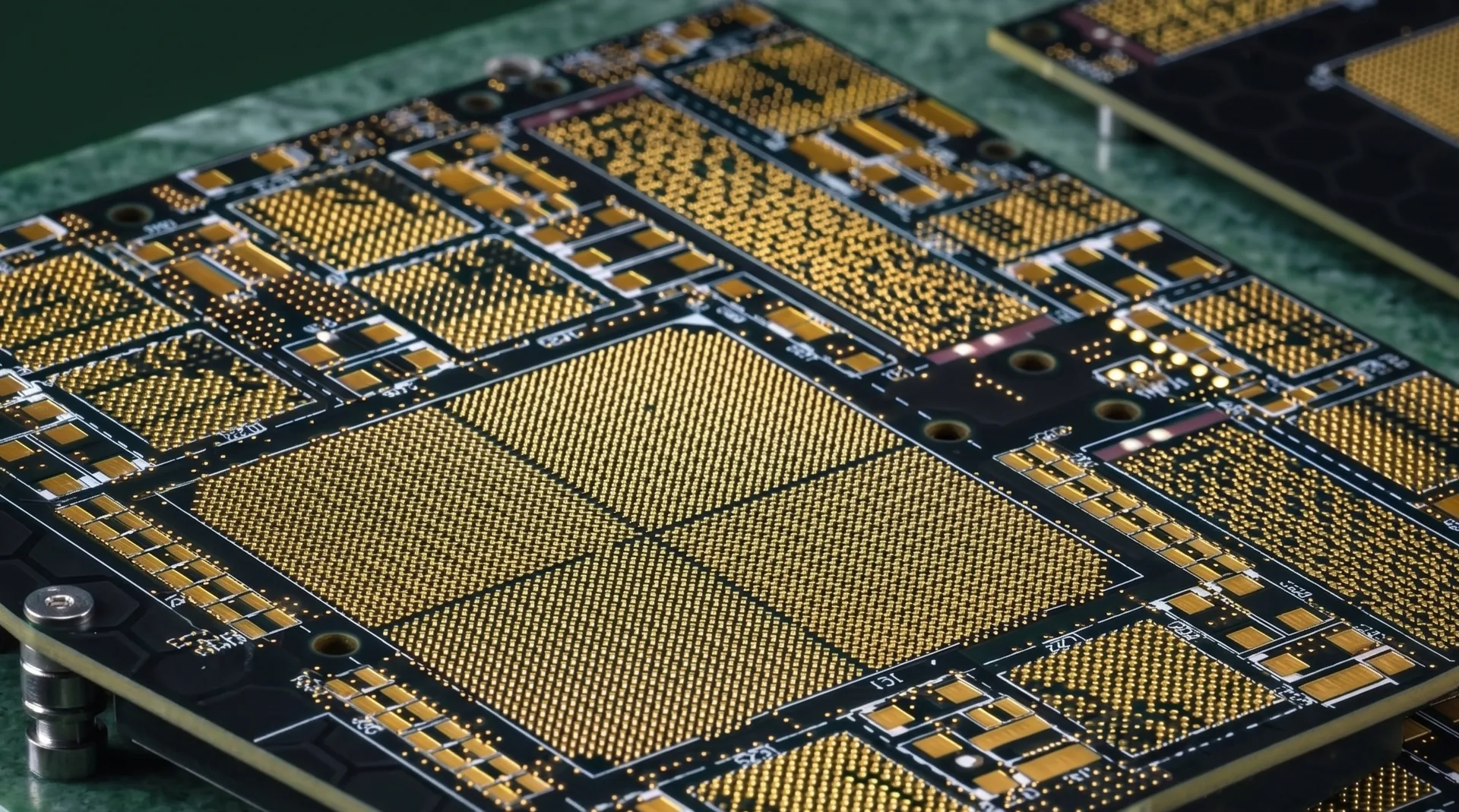
High-pin-count BGA assembly
- Reflow profiles validated per BGA package — large body parts have a non-trivial thermal lag.
- X-Ray at 100% on critical lots; quantitative voiding measured against IPC-7095 thresholds.
- Underfill applied on customer request; required on parts subject to mechanical shock or high CTE mismatch.
- Rework supported with documented profile and post-rework X-Ray; BGA placement rules must respect adjacent components for tool clearance.
Power integrity and decoupling — assembly notes
High-density decoupling caps (large counts of small body parts) require disciplined paste deposition; 100% SPI catches early.
Cavity / stitching capacitor placement under BGAs benefits from X-Ray sampling on first article.
Inrush controllers and hot-swap circuits validated under FCT before shipment.
Mechanical and cooling interface manufacturing
Thermal interface material (TIM) application with controlled thickness; TIM2 supported.
Backplate and stiffener installation.
Mounting hardware kitting per shipment when requested.
What to think about before files arrive
- Provide reflow profile constraints if you have them; otherwise we will propose one.
- Identify all high-power BGAs explicitly — they drive the profile and the X-Ray plan.
- Mark all components that must be hand-placed or post-soldered (post-reflow connectors).
- Provide FCT script or test plan; expect us to design the fixture in-house.
- Identify mechanical interfaces (heatsinks, brackets) and which side of the line installs them.
- Specify TIM and BOM hardware (screws, washers, standoffs) explicitly.
Documentation we produce per program
Reflow profile records per program.
X-Ray reports per lot, with voiding statistics.
FCT logs per serial.
Heatsink torque records per shipment.
Stackup confirmation and impedance reports for high-speed designs.
Common pitfalls we see in computing handoffs
- 1. Stackup provided as a thickness only — no insertion loss budget, no impedance targets per net class.
- 2. BGA placement too close to a stiffener — rework requires removing adjacent parts.
- 3. FCT script delivered after first article ship date — production stalls on validation gating.
- 4. Mechanical hardware not in BOM — kitting cannot complete on time.
- 5. TIM type assumed; supplier substitution causes thermal regression on the first system test.
Representative cases
- Dual-socket server motherboard — 16-layer high-TG PCB, double-sided BGA, 100% X-Ray.
- Edge AI compute module PCBA — thermal and stress validation under sustained load.
- PCIe Gen4 network card PCBA — low-loss laminate, controlled-depth drilling, validated SerDes link test.
Next step
Send your manufacturing package to start scope review.